
Definition of a Mechanical Power Press
Just what is meant by the term Mechanical Power Press and what is the function of a press?
Metal in sheet or coil form is formed, drawn, trimmed, blanked, or pierced between the upper and bottom sides of a press tool called a die to create stamped components. One half is clamped or affixed to the bed or bolster, while the other half is hooked to a slide. The component’s size and shape are programmed into the die so that it can be used over and over to make as many parts as needed for mass manufacturing. The press is used to join the two parts of the die. Because of the importance of repeatability and tolerance in the final stamped and assembled item, force (load) and accuracy are both necessary for success.Definition of mechanical power press.
You may get stampings made of just about everything. Aluminum is used to make beverage cans, high-strength steel is used to make various auto parts, and brass is used to make door handles and lock systems. Galvanized steel is used to stamp structural components like nail plates and joist hangers.
Setting the Press Size for the Die
There are two computations that must be made in order to fit a die to a press. Tonnage (or force) is the first, while the energy used is the second. The bottom dead center (BDC) to BDC in a single press cycle is used to measure how much force a press can exert.
It is important to distinguish between the energy produced by a press’s flywheel and the press’s tonnage rating. The press maker supplies a tabulated energy graph for each press, and these graphs vary widely from press to press. This is because the amount of energy a given size flywheel can generate is tied directly to the drive ratio. The price of a press is significantly affected by this as well.
Careful analysis is required before settling on die size. Many engineers, especially those that specialize in either die design or production or press procurement but lack broad knowledge, fall into the trap of ignoring the other calculation. By then, it’s too late to ask, “Why can’t we run this part?”
To Activate Drives and Cases
Mechanical, hydraulic, servo, and pneumatic are the four primary types of presses. Named after the mechanism that applies pressure (force) to the die to create the final stamping, each class is based on how that force is generated. Both the straight-side and C-frame options are available for each class. Single or dual ram connections are available for both varieties of the press. It is up to the manufacturer to decide if the added expense of a double-ram connection for a low-tonnage press is warranted in order to achieve the desired level of precision.
Two sides and four to eight sliding guides characterize straight-side presses. This lessens deflection and improves their ability to deal with non-centrifugal stresses.
Illustration of a non-geared drive system
First, a figure. The flywheel, clutch, and brake of a non-geared drive all attach to the eccentric or crankshaft. Full press energy is generally accessible between 50 and 100% of the maximum press speed.
Most C-frame presses are still run by hand and have a form like a letter C or G. Deflection under off-center loads is greater in a C-frame press than in a straight-side press because of the press’s open design. Two box guides or V-guides hold the slide in place.
Transfer presses, hydroformed presses, hot forge presses, and friction screw presses are all examples of specialized presses.
Transmissions that Power a Press Mechanically
Flywheel, single-geared, double-geared, double-action, link (sometimes called alternative slide motion [ASM]), and eccentric-geared mechanical presses are all distinct types of drive transmission that exert force on the die.
Everything is driven by an electric motor connected to a sizable flywheel. Multiple sorts of drives can be used to release the energy stored in the flywheel. The energy stored in the flywheel is depleted as the press completes a full stroke of 360 degrees each time a part is formed in the die.
As a result, the flywheel slows by an average of 10%-15%. On the upstroke of the press, the electric motor puts that energy, which had been wasted, back into the flywheel. In this way, the press is always prepared for the following round of production.
The press will slow down too much if the percentage of slowing caused by the flywheel, expressed as a percentage of strokes per minute (SPM), is greater than 15%. The press will become jammed on BDC after a few strokes. This happens if there is a miscalculation in the die’s tonnage or energy.
A clutch and brake, operated by electronic control, disengage the press’s flywheel from its drive, allowing for smooth stopping and starting of the press. Pneumatic or hydraulic releases are more common than spring-applied ones in clutches and brakes. Because of this, the press’s maximum speed and the operator’s and die’s safety depend on the clutch and brake’s stopping time.
Flywheel drive, in a mechanical press, Progressive dies are used for piercing, blanking, bending, and very shallow drawing on presses with flywheel drives. Press tonnage is typically between 30 and 600 tons. They operate at very quick rates, ranging from 125 to 250 SPM on the low end to over 1,000 SPM on the high end.
Since press speed is directly proportional to the length of the press stroke, this value is always kept as low as possible. The typical length of a stroke is about 2. An additional flywheel can be integrated into the driving system to provide additional energy at low speeds. But the power will never equal that of a geared press.
The normal full-tonnage rating for a flywheel-driven press is 0.062 inches between the bottom dead center (BDC) of the press cycle and the BDC of the same press cycle. On the eccentric or crankshaft are the flywheel, clutch, and brake. Full press energy is generally accessible between 50 and 100% of the maximum press speed. In any case, it’s best to double-check with the press’s maker just to be sure.
In cases when the material is thicker than the press’s rated capacity, die calculations must be double-checked. High snap-through (reverse loading) and press vibration can be avoided with some preparation.
When employing a flywheel press, the upper die and press slide (ram) weight is dynamically balanced by an opposing force. Without this barrier, the press could theoretically move at breakneck rates as it walked around the court.
Simple gear schematic
Contract stampers in the automotive industry use this press drive more than any other. Standard press speeds range from 40 to 80 SPM; however, they can be run continuously at speeds as low as 28 SPM.
Mechanical presses using two or more gears
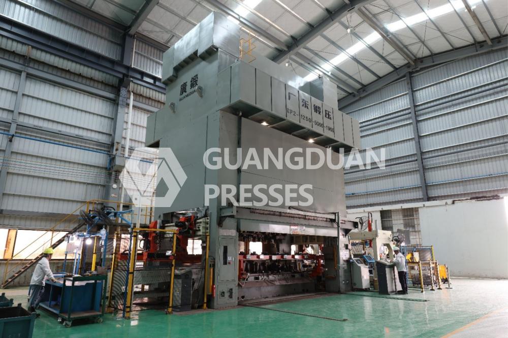
Mechanical press like Guangduan Straight Side Double Point Multi Station Press GD2 with two sets of gears. When a steady rate of production is required but cannot exceed 28 SPM, this press is put to use. It excels in demanding tasks, such as the stamping of high-strength steel. The press is slower than both the flywheel and a single-geared press, but the driving gear ratio keeps the flywheel spinning at the same pace.
This form of drive can create a very high energy, depending on the size of the flywheel. The press has a capacity of 200-1,600 tons and is attached to the slide in a two-point configuration. The most common mechanical presses are double-gear presses, which are used to press metal sheets and other materials. Double-gear presses have many advantages over single-gear presses, including greater efficiency and lower noise levels.
Presses with two sets of gears are ideal for transfer die manufacturing. Normal transfer rates range from 15 to 30 SPM. This drive is often used in presses with a BDC-to-BDC rating of 0.500 inches. For drawing, shaping, blanking, and piercing with transfer and progressive dies, some presses come equipped with a specific drive rated at 1 in. from BDC to BDC.
A link drive, which utilizes a sliding mechanism, can be substituted for the standard motor. In a different take on the classic slide mechanic, you can use a link drive. During the functional period of the press cycle, slide velocity can be slowed with this option. It also has the potential to improve output by as much as 25%.
A Machine with an Eccentric Gear Set
This press-and-drive combination is employed in applications that call for a stroke of more than 24 inches. This drive system has the same capabilities as a double-geared press, but the accuracy isn’t quite as excellent as an eccentric-shaft press due to the clearance with the gear train arrangement and the additional clearance needed in the slide guiding gib adjustment.
It’s a double-action slide. The press uses a pair of slides, with one slide nesting inside the other. There are two attachment points for the eccentric shaft on each slide. Since their strokes are distinct and synchronized, the outer slide functions as the blank holder, and the inner slide finishes the drawing process.
Diagram of a Double-Gear Drive System
When the required rate of output is less than 28 SPM, this drive is put to use. It excels in demanding tasks, such as the stamping of high-strength steel.
The deep-draw process, as in the production of beverage cans, requires the use of a press with two sets of sliding actions. To add to that, it’s the primary press in a line dedicated to drawing the body panels of automobiles.
CONTACT US

Guangdong Metal Forming Machine Works Co., Ltd.
We are always providing our customers with reliable products and considerate services.
If you would like to keep touch with us directly, please go to contact us
-

Home
-

Tel
-

Email
-

Contact