
Automotive Parts Forging Press Pressure and Stroke Control Explained
Stable operations in metal forming require consideration of pressure and stroke control in automotive applications. Insufficient or excessive forming loads can result in a variety of adverse effects including the formation of incomplete profiles, distortion in the dimensions of formed profiles, and an increase in die wear, surface defects, and the formation of cracks.
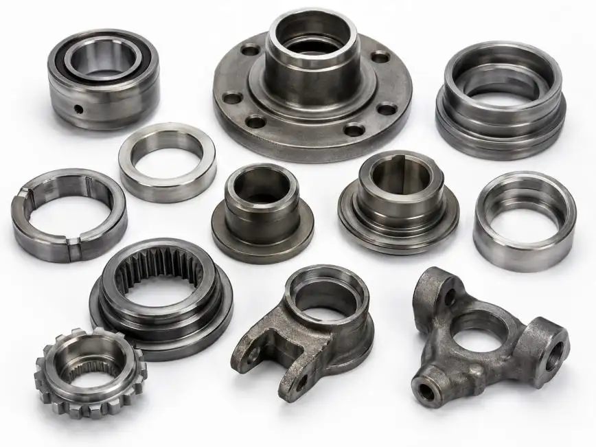
Control of stroke settings is also important. Travel of the slide or the closing height of the die can impact die closure and alignment in the absence of adequate slide guidance.
An Automotive Parts Forging Press should integrate capacity, slide stroke, die height, guidance, and other factors within the constraints of forming loads to achieve a desired level of productivity in a given operating mode. A press is neither adequate, nor in excess of, requirement based solely on nominal tonnage.
What Is Pressure Control?
Pressure control in the context of an Automotive Parts Forging Press refers to the control of the forming load within press, tooling, and process constraints. This control is not achieved simply by selecting a press with a significant tonnage capacity.
Nominal Capacity vs Actual Forming Load
Nominal capacity is the maximum allowable force available at a specified crank angle or slide position. In a mechanical press, available force changes as the crankshaft rotates.
Actual forming load is influenced by:
• Material grade, strength, and thickness
• Part projection area
• Forming depth and deformation ratio
• Die geometry and clearance
• Friction and lubrication
• Material temperature
• Slide speed
• Blanking, bending, drawing, or sizing requirements
The required load should include a reasonable engineering margin. While an oversized Automotive Parts Forging Press may seem advantageous, it will increasingly burden the budget, consume more energy, increase tooling and more floor space, and offer no benefit to part quality.
Impact of Overload Protection
There are many causes of unexpected loads and they range from poor lubrication and simply double feeding, to excessive material thickness, die obstruction and poor die adjustment.
Some of the protective benefits of an overload protection system are:
• Protection of slide, tooling and the crankshaft and connecting rods
• Damage control of abnormal feed
• Protection from the effects of excessive load for extended periods
• Improved recoverability of production after an overload event
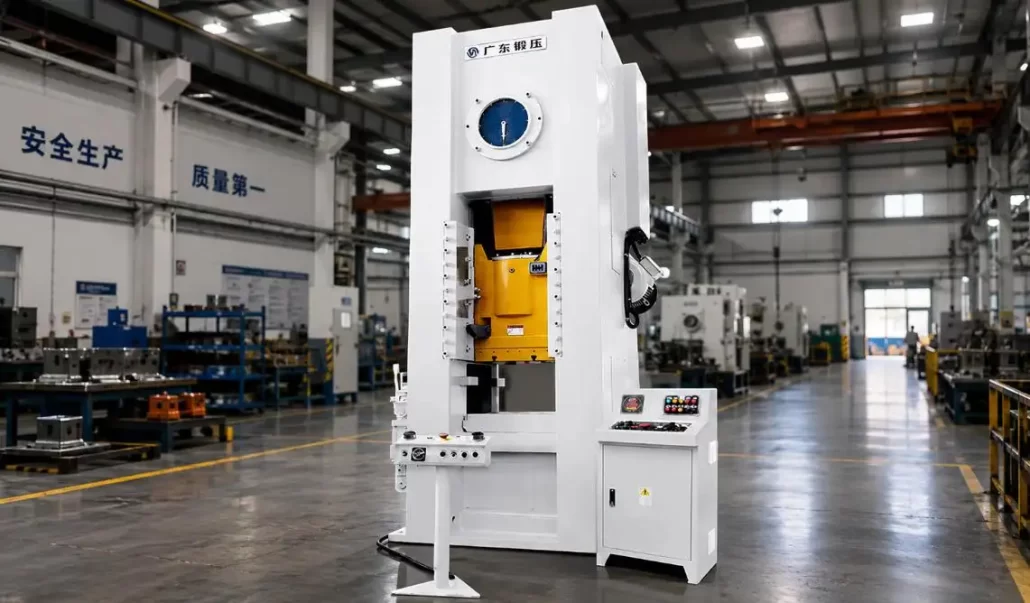
Hydraulic overload protection is used for higher capacity applications on the GUANGDUAN JH31-400, JH31-630 and JH31-800 models.
Basics of Stroke Control
When deciding on the specifics of an Automotive Parts Forging Press, Three responsive parameters need to be considered.
| Parameter | Definition | Production Impact |
| Slide Stroke | Distance between top and bottom dead center | Determines die opening and available forming movement |
| Strokes per Minute | Number of complete press cycles per minute | Affects production rate and feeder synchronization |
| Die Shut Height | Tooling installation height at bottom dead center | Determines die compatibility and final closure position |
The stroke distance is also important when considering part ejection and the transfer of material. Too excessive a stroke can negatively impact production.
The correct stroke should therefore match:
• Tool height and construction
• Required forming depth
• Material feeding direction
• Part removal method
• Ejector or transfer-system requirements
Three Operating Modes for Automotive Production
Continuous Stroke
Continuous stroke is commonly used for:
• High-volume production
• Coil-fed materials
• Automatic feeding systems
• Progressive dies
• Stable, repetitive operations
In this mode, the slide, feeder, clutch, brake, sensors, and safety system must operate in a synchronized sequence.
Single Stroke
Single Stroke mode executes one full cycle per command. It is useful for:
• Creating prototypes
• Short runs
• First-piece checks
• Loading by hand
• Testing out the process
It enables the operator to conveniently confirm the quality of both the tooling and the part prior to the start of full production.
Micro-Motion or Inching
Micro-motion allows the slide to move in controlled increments. It is primarily used for:
• Die installation
• Tool alignment
• Bottom-dead-center verification
• Feed-position adjustment
• Maintenance and troubleshooting
Micro-motion is an adjustment function rather than a normal production mode.
How Pressure and Stroke Work Together
Pressure and stroke should never be evaluated independently.
Load Position
Forming load often increases rapidly as the slide approaches bottom dead center. The selected Automotive Parts Forging Press must provide sufficient capacity at the crank angle where the main forming operation occurs.
Die Opening
The stroke must provide enough space for material entry, tool opening, part ejection, and component transfer.
Slide Speed
Slide speed influences:
• Material flow
• Friction and heat generation
• Springback
• Impact loading
• Surface quality
• Die service life
Die Height
Incorrect die-height adjustment may cause incomplete forming, overload, dimensional instability, or tool collision.
Eccentric Loading
Even with suitable tonnage and stroke, off-center loading can tilt the slide and create uneven die wear. Frame rigidity and guideway design are therefore important evaluation factors.
Why Slide Guidance Affects Repeatability
Automotive components often require stable dimensional performance across long production runs. Excessive slide clearance or lateral movement can cause:
• Upper and lower die misalignment
• Uneven wall or material thickness
• Localized tool wear
• Excessive burrs
• Unstable dimensions
• Reduced die life
A four-surface full-guideway structure can restrict lateral slide movement and support alignment throughout the stroke.
The GUANGDUAN JH31 Series uses four-surface slide guidance. Actual accuracy still depends on tooling design, press installation, lubrication, guideway condition, and preventive maintenance.
Die-Height Adjustment and Digital Indication
Different dies require different shut heights. Mechanical adjustment allows an Automotive Parts Forging Press to accommodate tooling within its specified die-height range.
Digital indication can improve:
• Setup repeatability
• Tool-change efficiency
• Position recording
• Operator communication
• Production standardization
After every die change, operators should still use micro-motion, conduct trial pressing, measure the first part, and verify the feeding position before continuous operation.
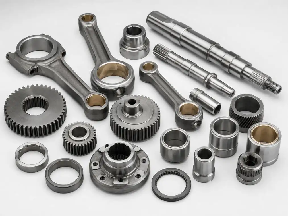
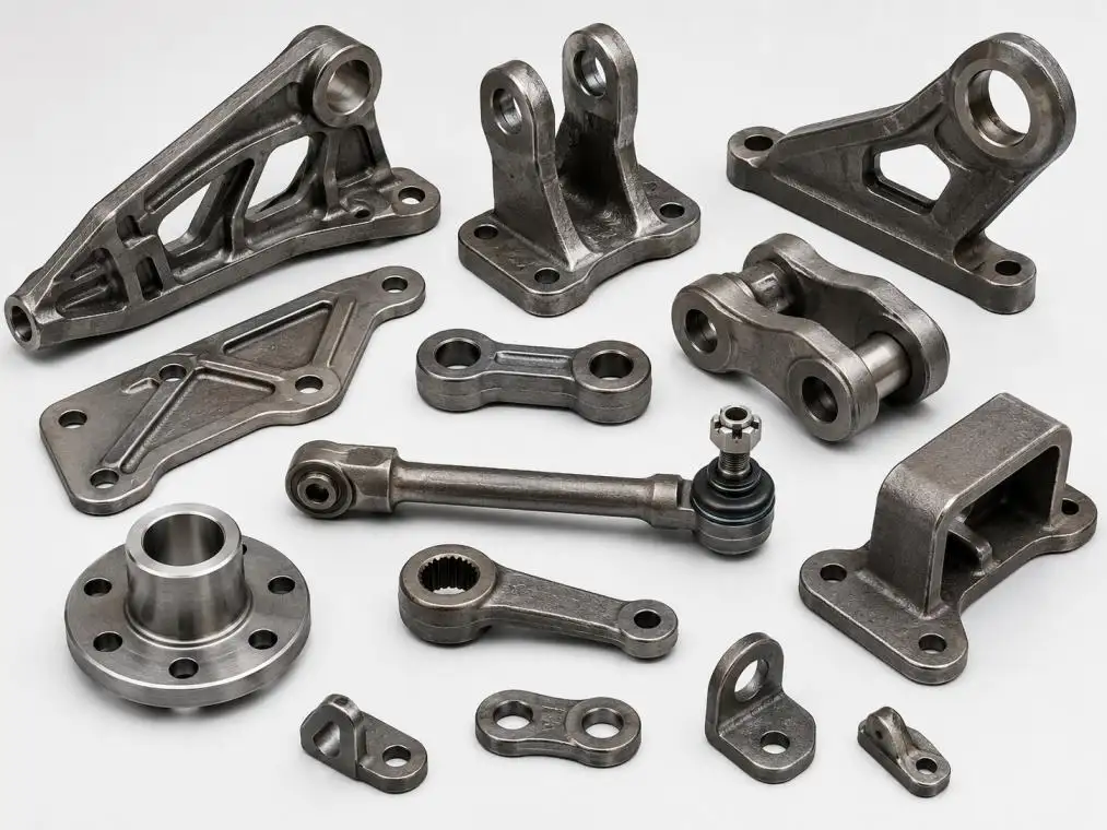
Requirements for Common Automotive Components
| Automotive Part | Pressure-Control Priority | Stroke-Control Priority |
| Brackets | Avoid overload and edge cracking | Stable bottom position |
| Reinforcement Plates | Calculate total forming load | Maintain parallel closure |
| Gear Blanks | Support concentrated high loads | Control final die position |
| Bushings and Rings | Prevent localized overload | Provide ejection clearance |
| Covers and Housings | Control flow and wrinkling | Match drawing depth |
| Small Chassis Parts | Synchronize load and feeding | Maintain continuous-cycle timing |
Final settings must be calculated from the material, thickness, geometry, tooling, and production sequence.
Common Pressure and Stroke Issues
| Problem | Possible Cause | Recommended Check |
| Insufficient Loading | High shut height | Verify spring and die settings |
| Cracks In Part | High friction, speed, or force | Increase lubrication and reduce speed |
| Thickness Variation | Die misalignment or eccentric loading | Examine tooling and guidance |
| Increased Die Wear | Overload, impact, or bad alignment | Examine load and feed position |
| Double Feeding | Out of sync feeders | Examine PLC, sensors, and the feeding units |
| Loose Dimensions | Variation of guides and die height | Inspect adjusters and guideways |
PLC Control and Automated Systems
Pneumatic and PLC systems control stroke modes, safety interlocks, clutches, brakes, and ancillary equipment.
An entire automated line for Automotive Parts Forging Press may include:
• Feeding systems that are automatic
• Uncoilers
• Leveling systems
• Material inspector
• Photoelectric sensors
• Die monitors
• Part ejection systems
• Fault-stop systems
Simply adding a feeder does not make a system automated. A system will also require material handling, tool monitoring, inspection, and a safety interlock system.
Closing Words
Reliable production demands more than rated tonnage; it requires integrated control of pressure, stroke, die height, slide guidance, feeding, tooling, and safety.
GUANGDUAN’s JH31 Series Automotive Parts Forging Press incorporates a rigid closed-frame construction, wet clutch, four-surface slide guidance, die height adjustment with a digital readout, and PLC-pneumatic control. It enables continuous operation as well as single and incremental strokes. It may also be equipped with photoelectric safety devices, and additional systems for automatic feeding, uncoiling, and leveling can be integrated on the press.
To provide an appropriate configuration, please send the diagrams of the related components and the technical specifications of the materials, tools dimensions, forming forces, output requirements, and the desired level of automation.
FAQs
Q1. What is the application of the GUANGDUAN JH31 Series?
The JH31 Series is useful for stamping, setting, blanking, and other forming and processing of metal operations used in manufacturing automotive, motorcycle, hardware, and gas appliances and their related instruments.
Q2. What kind of structure is used in the JH31 series?
The JH31 Automotive Parts Forging Press uses a closed single-point design with a rigid box type body and a narrow table. Some models may use a four-pull-rod pre-stressed structure.
Q3. Why is it important to have a rigid frame for an Automotive Parts Forging Press?
High rigidity of the frame press reduces the chances of uneven wear to the dies in operation, increases dimensional repeatability, and maintains alignment of the dies.
Q4. What are the available operating modes?
The JH31 Series has three available operating modes: continuous stroke, single stroke, and micro-motion. The first mode is for mass production. The second is for forming and setting dies, and the last one is for maintenance.
Q5. How is die height changed in the JH31 Series?
Die height is changed in the JH31 Series by a mechanical process and is read off a digital display. This helps operators by providing a way to take record settings, calibrate the dies faster, and provides an overall better repeatability for the setup.
CONTACT US


Guangdong Metal Forming Machine Works Co., Ltd.
We are always providing our customers with reliable products and considerate services.
If you would like to keep touch with us directly, please go to contact us
-

Home
-

Tel
-

Email
-

Contact