OUR PRODUCT
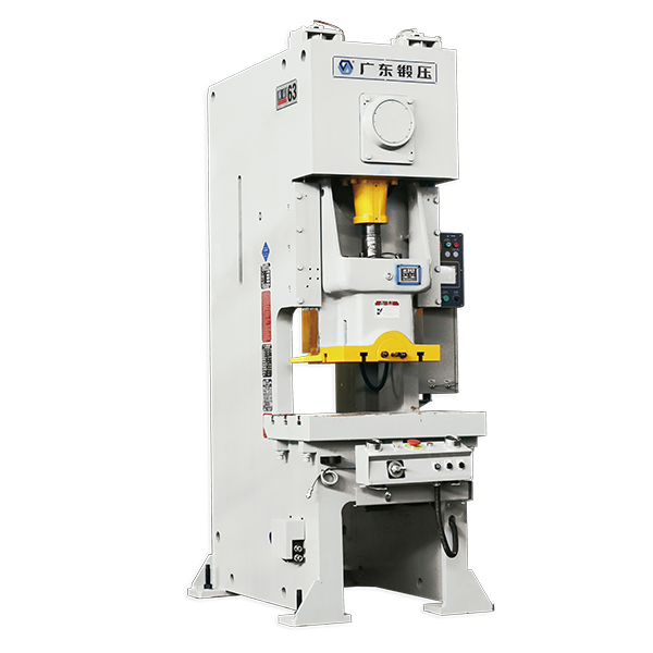
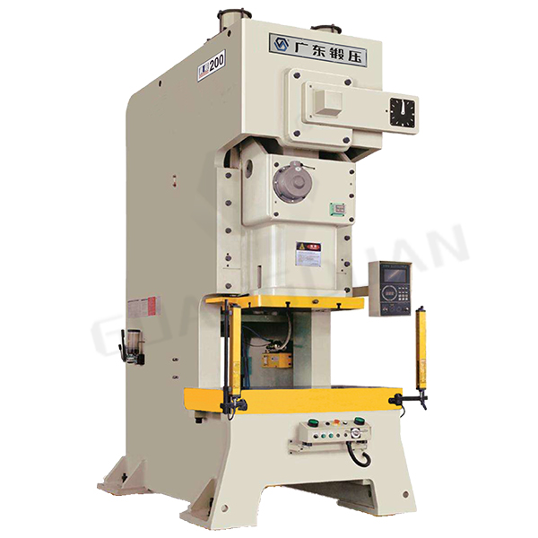
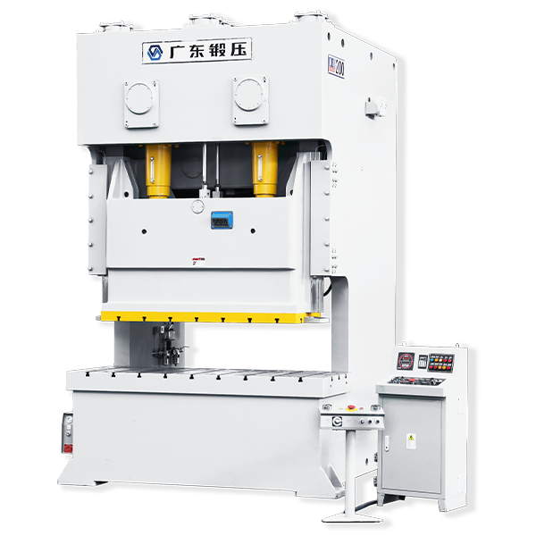
Two-point/Four-point Single Acting Precision Mechanical Press
The machine body is manufactured through welding the steel plates, after which the high-temperature annealing is conducted, so the rigidity is good and stability of the precision of the complete machine is high.
It is provided with the self-mowing work table and the die clamping system, and the die change efficiency is improved.
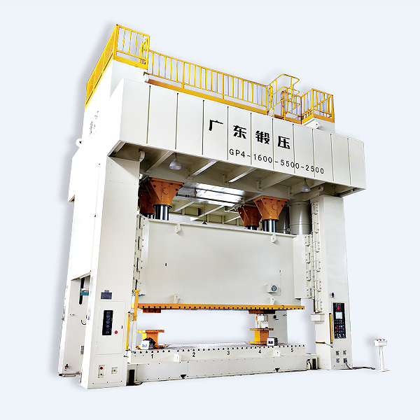
STRAIGHT SIDE GP2/4 SERIES
TWO-POINT/FOUR-POINT SINGLE-ACTING PRECISION MECHANICAL PRESS
The machine body is manufactured through welding the steel plates, after which the high-temperature annealing is conducted, so the rigidity is good and stability of the precision of the complete machine is high.
It is provided with the self-mowing work table and the die clamping system, and the die change efficiency is improved.
The slide adopts the eight-surface long-guideway guiding, so the precision is stable and thereby ensuring stability of production and good quality of products.
The electrical devices adopt the PLC control method, which can achieve the automatic adjustment of air pressure, die set height and air cushion stroke and so on and the automaton degree is high.
The main transmission structure adopts the transmission structure of five shafts towards different directions. The gears are arranged symmetrically and the guide pillar and the guide sleeve are provided.
It is provided with the air cushion with the large tonnage and pure gas, so it can satisfy various kinds of blank pressing and ejection demands.
It adopts the progressive thin oil automatic circulating lubricating system and possesses the automatic monitoring functions of pressure, rate of flow temperature, oil level and dogging resistance and so on.
It can be provided with the automatic feeding device and undoing leveling device to achieve automated stamping production of a single machine.


|
|
GP2-300 |
GP2-400 |
GP2-500 |
GP2-630 |
GP2-800 |
GP2-1000 |
GP2-1200- |
|
A |
120 |
120 |
150 |
150 |
150 |
150 |
150 |
|
B |
240 |
240 |
240 |
300 |
300 |
300 |
300 |
|
C |
9 |
11 |
11 |
11 |
11 |
13 |
13 |
|
D |
120 |
120 |
120 |
150 |
150 |
150 |
150 |
|
E |
60 |
60 |
60 |
75 |
75 |
75 |
75 |
|
F |
35 |
35 |
35 |
40 |
40 |
40 |
40 |
|
M |
5 |
5 |
7 |
5 |
7 |
7 |
7 |
|
N |
17 |
19 |
19 |
19 |
21 |
23 |
23 |
|
|
GP4-500 |
GP4-630 |
GP4-800 |
GP4-1000 |
GP4-1000 |
GP4-1200 |
GP4-1600 |
|
A |
150 |
150 |
150 |
150 |
150 |
150 |
150 |
|
B |
300 |
300 |
300 |
300 |
300 |
300 |
300 |
|
C |
11 |
11 |
11 |
11 |
13 |
13 |
13 |
|
D |
150 |
150 |
150 |
150 |
150 |
150 |
150 |
|
E |
75 |
75 |
75 |
75 |
75 |
75 |
75 |
|
F |
40 |
40 |
40 |
40 |
40 |
40 |
40 |
|
M |
7 |
7 |
7 |
9 |
9 |
9 |
9 |
|
N |
17 |
21 |
21 |
21 |
23 |
23 |
25 |

Main Transmission Structure
● The main transmission structure adopts the transmission structure of five shafts toward different directions. The gears are arranged symmetrically. And the inertia force of gears and side force of the connecting rod counteract mutually. so precision and stability of the equipment are increased effectively.
● Adoption of the five-shaft structure can enlarge the interval between the left pressure spot and the right pressure spot to the most degree and improve the unbalancing load resistance capacity of the equipment.
● For the main transmission the two-level reduction of the speed is adapted, the high-speed level of which uses the herringbone gear, while the low-speed level of which uses the straight gear. The small gear adopts the high-strength alloy steel and the large adopts NO.45 forged steel and corresponding heat treatment is conducted. Mean white, the hardness different between the large gear and the small gear is guaranteed, so strength of the gear is guaranteed and abrasive resistance is improve and hence the service life of the equipment is improved.
● The main transmission gear and the connecting road are sealed inside the bean. In accordance with the work characteristic of the gear’s heavy duty at the low speed, the progressive thin oil automatic lubricating system is adopted to conduct the forced lubrication, so wear is reduced and noise is lowered effected and reliability of the equipment is improved.
Technical Features of The Air Cushion
● The air cushion adopts the single apical cap and pure gas type structure and it is composed of an apical cap, two suits of main cylinders, a set of stroke regulating mechanism, a buffering mechanism and a set of lag latching cylinder (purchase on selection) and so on.
● The air cushion is provided with the stroke regulating device. A set of ejector rob with the standard length only can satisfy demands of ne different awing processes, which avoids changing the ejector rob frequently and improves the work efficiency.
● The air cushion is provided with the hydraulic terminal buffering function, which can reduce impact, lower noise from work and prolong the service life of the equipment effectively.
● The air cushion adopts the progressive interval type thin oil automatic lubricating system to conduct the forced lubrication, so stability can be guaranteed even if there is a long-period full load.
● The air cushion can be provided with the lag latching cylinder selectively so as to satisfy demands of the special drawing process and thereby preventing the work piece being destroying by the extremely rapid rising of the air cushion.

No information.
GP2 SERIES PRODUCT PARAMENTERS
|
GP2-400 |
GP2-500 |
GP2-630 |
GP2-800 |
GP2-1000 |
GP2-1250 |
GP2-1600 |
||||||||||||||
| Nominal Capacity | kN |
4000 |
5000 |
6300 |
8000 |
10000 |
12500 |
16000 |
||||||||||||
|
Rating Point A.B.D.C. (Above bottom dead center) |
mm |
13 |
13 |
13 |
13 |
13 |
13 |
13 |
||||||||||||
| Stroke length | mm |
400 |
600 |
800 |
500 |
600 |
800 |
550 |
800 |
650 |
600 |
550 |
700 |
600 |
||||||
| Strokes per minute | continuous | SPM |
12-25 |
15-28 |
15-25 |
10-20 |
15-25 |
15-25 |
15-25 |
10-18 |
10-20 |
10-18 |
15-28 |
12-22 |
10-16 |
11-18 |
||||
| interrupted | SPM |
15 |
15 |
11 |
10 |
12 |
10 |
10 |
11 |
9 |
10 |
9 |
9 |
8 |
9 |
|||||
| Slide Bolster area | LR | mm |
3000 |
3450 |
3800 |
4000 |
3600 |
3800 |
4000 |
4500 |
4000 |
4500 |
6000 |
5000 |
6000 |
5500 |
||||
| FB | mm |
1400 |
1600 |
1800 |
2000 |
1500 |
2000 |
2000 |
2000 |
1800 |
1800 |
1700 |
1800 |
1800 |
1800 |
|||||
| Max. die height | mm |
800 |
1000 |
1200 |
1200 |
900 |
1200 |
1200 |
1200 |
1200 |
1000 |
1000 |
1200 |
1300 |
1300 |
|||||
| Slide adjustment | mm |
200 |
500 |
600 |
600 |
300 |
600 |
600 |
400 |
400 |
550 |
400 |
550 |
600 |
600 |
|||||
| Max. Weight of upper mold | ton |
5 |
8 |
10 |
15 |
10 |
12 |
15 |
15 |
20 |
20 |
25 |
20 |
25 |
20 |
|||||
| Upper mold clamps
(Option: manual / auto) |
kN |
60KN×10 |
60KN×10 |
80KN×10 |
80KN×20 |
100KN×12 |
100KN×12 |
100KN×12 |
||||||||||||
| Movable bolster |
Direction / Quantity (Option: Fixed bolster) |
Structural form of the work table: backward and forward movement leftward and rightward movement and number, all of which are selected by the customer
|
||||||||||||||||||
| Bolster area | LR | mm |
3000 |
3450 |
3800 |
4000 |
3600 |
3800 |
4000 |
4500 |
4000 |
4500 |
6000 |
5000 |
6000 |
5500 |
||||
| FB | mm |
1400 |
1600 |
1400 |
1600 |
1500 |
2000 |
2000 |
2000 |
1800 |
1800 |
1700 |
1800 |
1800 |
1800 |
|||||
| Height of Bolster | mm |
700 |
700 |
700 |
750 |
750 |
750 |
750 |
||||||||||||
| Bearing capacity of Bolster area | ton |
10 |
16 |
20 |
40 |
20 |
25 |
40 |
30 |
40 |
40 |
50 |
40 |
50 |
40 |
|||||
| Moving speed | Customized | m/min |
1.5-12 |
1.5-12 |
1.5-12 |
15.-12 |
1.5-12 |
1.5-12 |
1.5-12 |
|||||||||||
| Pin lifting capacity | kN |
15 |
15 |
15 |
15 |
15 |
15 |
15 |
||||||||||||
| Pin lifting stroke length | mm |
160 |
160 |
160 |
160 |
160 |
160 |
160 |
||||||||||||
| Air cushion | Type | Customized |
Single apical cap/having the latching(having the latching function or not selected by the customer) |
|||||||||||||||||
| Capacity | kN |
450 |
600 |
1000 |
1500 |
1500 |
2000 |
3000 |
||||||||||||
| Stroke length | mm |
0-200 (Adjustable) |
0-200 (Adjustable) |
0-250 (Adjustable) |
0-250 (Adjustable) |
0-250 (Adjustable) |
0-250 (Adjustable) |
0-30 (Adjustable) |
||||||||||||
| Machine height above ground | mm |
6500 |
6800 |
7100 |
8850 |
8100 |
8400
|
8925 |
8800
|
9100 |
9550 |
9800 |
9550 |
9800 |
9800 |
|||||
| Machine dimensions | LR | mm |
4850 |
6540 |
6900 |
7000 |
6255 |
7550 |
7000 |
8250 |
7550 |
8250 |
9250 |
8300 |
9300 |
8800 |
||||
| FB | mm |
3100 |
3500 |
4900 |
5500 |
4430 |
5100 |
5500 |
5260 |
5260 |
5700 |
5600 |
5500 |
5500 |
5500 |
|||||
| Motor power | kW |
45 |
55 |
75 |
90 |
110 |
90 |
110 |
132 |
132 |
160 |
160 |
200 |
200 |
||||||
| Motor for slide adjustment | kW |
3 |
5.5 |
4 |
5.5 |
7.5 |
7.5 |
7.5 |
11 |
11 |
18.5 |
|||||||||
| Press height beyond ground | mm |
4500 |
4500 |
5000 |
6000 |
6000 |
6000 |
6000 |
||||||||||||
| Pit depth | ton |
90 |
100 |
145 |
150 |
165
|
170 |
175 |
260 |
240 |
310 |
350 |
350 |
400 |
430 |
|||||
| Air pressure used | MPa |
0.6 |
||||||||||||||||||
| Technical specifications |
GP2-630 |
GP4-800 |
GP4-1000 |
GP4-1000 |
GP4-1250 |
GP4-1600 |
GP4-2000 |
|||||
| Nominal Capacity | kN |
6300 |
8000 |
10000 |
10000 |
12500 |
16000 |
20000 |
||||
|
Rating Point A.B.D.C. (Above bottom dead center) |
mm |
13 |
13 |
13 |
13 |
13 |
13 |
13 |
||||
| Stroke length | mm |
600 |
700 |
800 |
1000 |
800 |
1000 |
800 |
||||
| Strokes per minute | continuous | SPM |
12-18 |
10-18 |
10-16 |
10-16 |
10-16 |
10-16 |
9-15 |
|||
| interrupted | SPM |
12 |
10 |
10 |
10 |
10 |
10 |
8 |
||||
| Slide area | LR | mm |
4000 |
4000 |
4000 |
4200 |
5500 |
4600 |
5500 |
|||
| FB | mm |
2000 |
2200 |
2200 |
2200 |
2500 |
2500 |
2500 |
||||
| Max. die height | mm |
1200 |
1300 |
1300 |
1400 |
1400 |
1400 |
1500 |
||||
| Slide adjustment | mm |
600 |
600 |
650 |
700 |
750 |
700 |
700 |
||||
| Max. Weight of upper mold | ton |
15 |
18 |
20 |
25 |
25 |
25 |
25 |
||||
|
Upper mold clamps (Option: manual / auto) |
kN |
80KN×10 |
80KN×10 |
100KN×10 |
80KN×20 |
100KN×12 |
100KN×12 |
100KN×16 |
||||
|
Upper mold clamps (Option: manual / auto) |
Direction / Quantity (Option: Fixed bolster) |
Structural form of the work table: backward and forward movement leftward and rightward movement and number, all of which are selected by the customer
|
||||||||||
| Bolster area | LR | mm |
4000 |
4000 |
4000 |
4200 |
6000 |
5200 |
5500 |
|||
| FB | mm |
2000 |
2000 |
2200 |
2000 |
2500 |
2500 |
2500 |
||||
| Bolster to ground | mm |
700 |
700 |
700 |
750 |
650 |
690 |
750 |
||||
| Load of bolster | ton |
30 |
35 |
40 |
50 |
50 |
50 |
50 |
||||
| Moving speed | Customized | m/min |
1.5-12 |
1.5-12 |
1.5-12 |
15.-12 |
1.5-12 |
1.5-12 |
1.5-12 |
|||
| Moving speed | kN |
15 |
15 |
15 |
15 |
15 |
15 |
15 |
||||
| Pin lifting stroke length | mm |
160 |
160 |
160 |
160 |
160 |
160 |
160 |
||||
| Cushion | Type | Customized |
Single apical cap/having the latching(having the latching function or not selected by the customer) |
|||||||||
| Capacity | kN |
1000 |
1500 |
1500 |
2000 |
1000+2500 |
3000 |
3000 |
||||
| Stroke length | mm |
0-250 (Adjustable) |
0-250 (Adjustable) |
0-250 (Adjustable) |
0-300 (Adjustable)
|
0-300 (Adjustable) |
0-300 (Adjustable) |
0-300 (Adjustable) |
||||
| Press height beyond ground | mm |
8300 |
8500 |
8800 |
10000 |
10000 |
10600 |
10600 |
||||
| Overall dimension | LR | mm |
5950 |
5950 |
7100 |
7300 |
9600 |
9500 |
9800 |
|||
| FB | mm |
5680 |
5750 |
6520 |
6520 |
7200 |
9500 |
9800 |
||||
| Main motor | kW |
90 |
110 |
132 |
180 |
200 |
250 |
315 |
||||
| Motor for slide adjustment | kW |
7.5 |
7.5 |
11 |
11 |
18.5 |
18.5 |
18.5 |
||||
| Pit depth | mm |
5800 |
6000 |
6000 |
6000 |
6000 |
6500 |
6500 |
||||
| Pit depth | ton |
235 |
280 |
325 |
360 |
400 |
450 |
500 |
||||
| Air pressure used | MPa |
0.6 |
||||||||||

STRAIGHT SIDE GP2/4 SERIES CNFIGURATION
Standard configuration
T-shape two-hand button operating board (movable)
Touching type supervising controller
Hydraulic overload protective device
Over-run protective device
Single 4-bit counter
Accumulative 8-bit counter
Preset 4-bit counter
Motor-driven side block adjustment device
Automatic lubricating device
Misfeed detecting interface
Electronic cam controller
Lighting lamp for die
Lighting lamp for the work area
Frequency conversion(DC)speed regulating equipment
Digital die height indicator
Clutch, brake
Side block and die balancing device
Movable work table
Electronic type crank angle indicator
Inversion set of the main motor
Coupling for air blowing
Coupling for air source
Double solenoid valve
Flywheel brake equipment
Safety cock
Optional configuration
Air cushion
Foot switch
Damping sizing block
Ejector device in the upper of the slide block
Quick die change device
Load detector
Die safety detector
CONTACT US

Guangdong Metal Forming Machine Works Co., Ltd.
We are always providing our customers with reliable products and considerate services.
If you would like to keep touch with us directly, please go to contact us
-

Home
-

Tel
-

Email
-

Contact