OUR PRODUCT
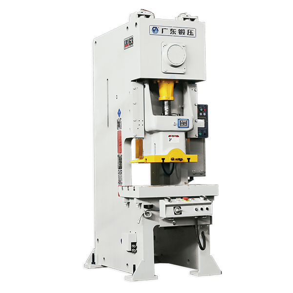
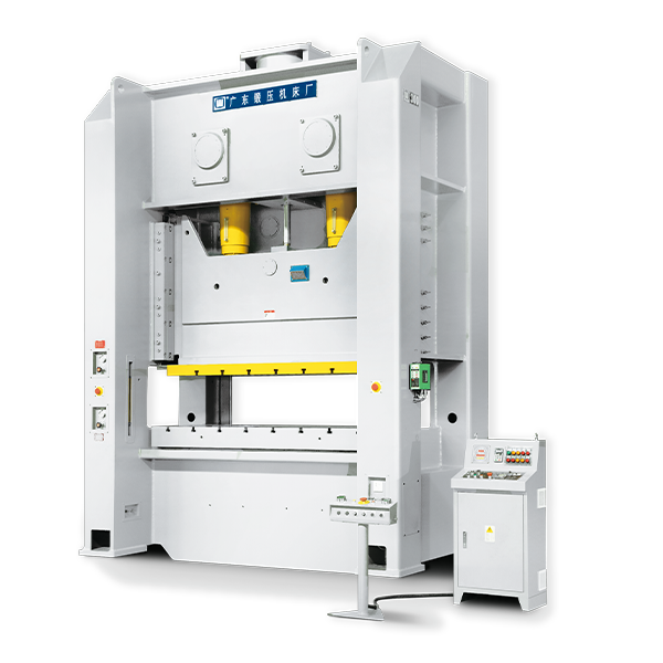
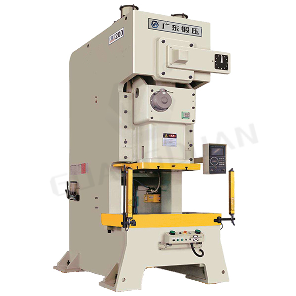
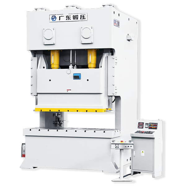
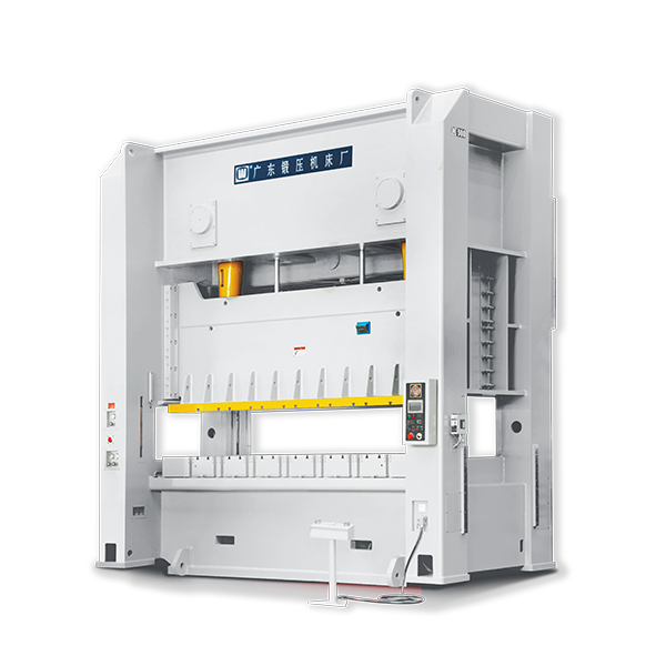
Open Back Mechanical Power Press Machine JH21 Series
The body of the mechanical power press machine is formed by welding steel plates, and is treated by artificial aging and shot blasting passivation, and anti-corrosion treatment. The deformation of the lathe bed is small and the rigidity is good.
How does Mechanical Power Press Machine Work?
Mechanical power press machines cut, stamp, form, or assemble metal or other materials with tools or dies attached to slides or plungers. Metalworking is done by placing the stock on the bottom die and tapping it with the top die. The upper die is connected to the crankshaft through a connecting rod, and the rotation of the crankshaft is completed by the motor, flywheel, and gear power transmission.
Features
- The combination of pneumatic wet friction disc clutch and brake makes the machine have the characteristics of long service life, low noise, and high safety. Both the gear pair and the sliding pair are heat treated, quenched, and precision ground, with smooth transmission and high precision.
- The mechanical power press machine adopts PLC control mode, and can also cooperate with the automatic feeding device to form a single-machine or multi-machine automatic stamping production line with high efficiency.
- The standard configuration of the mechanical power press machine is two-hand button operation, wet friction disc clutch manufacturing, hydraulic overload protection, adjusting motor, automatic lubrication system (models above 1100KN), and motor adjustment control height (models above 630KN).
- According to different production requirements, photoelectric protectors, constant speed motors, air cushions, output shafts, or mold protection devices can be chosen to install.
No information.
JH21 SERIES PARAMETERS 1
| Unit | JH21-25 | JH21-45 | JH21-63 | JH21-80 | JH21-110 | ||
| Nominal capacity | kN | 250 | 450 | 630 | 800 | 1100 | |
|
Rating Point A.B.D.C. (Above bottom dead center) |
mm | 2.8 | 3.2 | 4 | 5 | 5 | |
| Stroke Length | mm | 80 | 120 | 140 | 140 | 180 | |
| Strokes Per Minute | Fixed | SPM | 100 | 80 | 70 | 60 | 50 |
| Variable | SPM | 50-100 | 45-90 | 45-85 | 45-75 | 35-65 | |
| Max. die height | mm | 250 | 270 | 300 | 320 | 350 | |
| Slide adjustment | mm | 50 | 60 | 70 | 90 | 90 | |
| Depth of throat | mm | 210 | 225 | 270 | 290 | 350 | |
| Bolster Area (FB |
mm | 400×700 | 440×810
|
520×870
|
560×10000
|
680×1100
|
|
| Thickness of bolster | mm | 75 | 105 | 125 | 135 | 155 | |
| Bolster to ground | mm | 775 | 815 | 895 | 915 | 900 | |
| Distance between columns | mm | 470 | 510 | 560 | 670 | 700 | |
| Slide Area (FB LR) | mm | 250×360
|
340×410
|
400×480
|
450×560
|
520×630
|
|
| Shank hole(Diameter/depth) | mm | Φ40×60
|
Φ50×60
|
Φ50×65
|
Φ50×80
|
Φ60×80
|
|
| Motor power | kW | 3 | 5.5 | 5.5 | 7.5 | 11 | |
| Overall dimension | LR | mm | 1095 | 1155 | 1235 | 1425 | 1545 |
| FB | mm | 1485 | 1600 | 1690 | 1955 | 2150 | |
| H | mm | 2225 | 2680 | 2750 | 2910 | 3175 | |
| Total Weight (net) | kg | 2300 | 3700 | 4550 | 6500 | 9700 | |
| Cushion capacity | kN | 25 | 40 | 60 | 75 | 80 | |
| Cushion stroke length | mm | 40 | 50 | 60 | 65 | 80 | |
| Air pressure used | MPa | 0.6 | 0.6 | 0.6 | 0.6 | 0.6 | |
Remarks: specifications are subject to change without notice.
JH21 SERIES PARAMETERS 2
|
|
Unit |
JH21-125 |
JH21-160 |
JH21-200 |
JH21-250 |
JH21-300 |
JH21-400 |
|
|
Nominal capacity |
kN |
1250 |
1600 |
2000 |
2500 |
3000 |
4000 |
|
|
Rating Point A.B.D.C. (Above bottom dead center) |
mm |
5 |
6 |
6 |
6 |
6 |
8 |
|
|
Stroke Length |
mm |
160 |
200 |
250 |
250 |
250 |
250 |
|
|
Strokes Per Minute |
Fixed |
SPM |
50 |
45 |
35 |
35 |
35 |
— |
|
Variable |
SPM |
35-65 |
30-55 |
25-45 |
25-40 |
25-40 |
25-35 |
|
|
Max. die height |
mm |
350 |
400 |
470 |
500 |
500 |
550 |
|
|
Slide adjustment |
mm |
100 |
100 |
100 |
110 |
110 |
120 |
|
|
Depth of throat |
mm |
350 |
390 |
430 |
475 |
475 |
490 |
|
|
Bolster Area (FB |
mm |
680×1100 |
760×1300
|
840×1400
|
930×1500
|
930×1500
|
950×1800
|
|
|
Thickness of bolster |
mm |
160 |
165 |
175 |
185 |
185 |
205 |
|
|
Floor to Bolster |
mm |
920 |
915 |
995 |
1105 |
1105 |
1120 |
|
|
Bolster to ground |
mm |
700 |
850 |
880 |
930 |
960 |
1080 |
|
|
Slide Area (FB |
mm |
540×670
|
600×760
|
650×860
|
700×930
|
700×930
|
750×1200
|
|
|
Shank hole(Diameter/depth) |
mm |
Φ60×80
|
Φ60×90
|
Φ60×90
|
Φ60×100
|
Φ60×100
|
Φ70×100
|
|
|
Main motor |
kW |
11 |
15 |
15 |
22 |
22 |
37 |
|
|
Overall dimension |
LR |
mm |
1575 |
1740 |
1830 |
1875 |
1950 |
1890 |
|
FB |
mm |
2135 |
2505 |
2740 |
2980 |
3100 |
3220 |
|
|
H |
mm |
3310 |
3740 |
4100 |
4545 |
4565 |
4800 |
|
|
Total Weight (net) |
kg |
11000 |
15310 |
21000 |
28000 |
32000 |
36000 |
|
|
Cushion capacity |
kN |
100 |
100 |
120 |
140 |
160 |
160 |
|
|
Cushion Stroke length |
mm |
70 |
100 |
100 |
120 |
120 |
120 |
|
|
Air pressure used |
MPa |
0.6 |
0.6 |
0.6 |
0.6 |
0.6 |
0.6 |
|
Independent Electrical cabinet
Remarks: specifications are subject to change without notice.
DIMENSION OF THE WORKTABLE PLATE AND SLIDE BLOCK


| Dimension | JH21-25 | JH21-45 | JH21-63 | JH21-80 | JH21-110 | JH21-125 | JH21-160 | JH21-200 | JH21-250 | JH21-300 | JH21-400 |
| a | 105 | 130 | 140 | 150 | 150 | 180 | 260 | 300 | 350 | 350 | 450 |
| a1 | — | — | — | — | — | — | 160 | 170 | 200 | 200 | 250 |
| b | 125 | 140 | 150 | 180 | 250 | 250 | 300 | 320 | 360 | 360 | 360 |
| b1 | — | — | — | — | 150 | 125 | 150 | 160 | 180 | 180 | 180 |
| e | 150 | 195 | 235 | 270 | 275 | 290 | 250 | 320 | 350 | 350 | 500 |
| f | 100 | 130 | 150 | 180 | 200 | 210 | 220 | 250 | 270 | 270 | 270 |
| g | 65 | 75 | 75 | 75 | 90 | 90 | 100 | 100 | 100 | 100 | 100 |
| h | 60 | 100 | 100 | 75 | 90 | 90 | 100 | 100 | 100 | 100 | 100 |
| i(RL |
5×3 | 5×3
|
5×3
|
5×3
|
6×4
|
6×4
|
8×4
|
7×5
|
8×6
|
8×6
|
8×6
|
| j | Φ21 | Φ21 | Φ21 | Φ26 | Φ26 | Φ26 | Φ32 | Φ32 | Φ32 | Φ32 | Φ32 |
| k | 200 | 260 | 300 | 360 | 380 | 410 | 440 | 480 | 500 | 500 | 500 |
| l | 100 | 130 | 150 | 180 | 190 | 210 | 220 | 240 | 260 | 260 | 260 |
| m | Φ40 | Φ50 | Φ50 | Φ50 | Φ60 | Φ60 | Φ60 | Φ60 | Φ60 | Φ60 | Φ60 |
| n | 18 | 22 | 22 | 22 | 22 | 22 | 28 | 28 | 28 | 28 | 28 |
| p | 18 | 24 | 24 | 24 | 24 | 24 | 28 | 28 | 28 | 28 | 28 |
| q | 12 | 16 | 16 | 16 | 16 | 20 | 20 | 20 | 20 | 20 | 20 |
| r | 30 | 38 | 38 | 38 | 38 | 38 | 48 | 48 | 48 | 48 | 48 |
| u | — | — | — | 37.5 | 45 | 45 | 50 | 50 | 50 | 50 | 50 |
| v | — | — | — | 37.5 | 45 | 45 | 50 | 50 | 50 | 50 | 50 |
| x | 290 | 340 | 400 | 480 | 500 | 580 | 600 | 780 | 780 | 780 | — |
| y | 180 | 270 | 320 | 350 | 420 | 450 | 480 | 550 | 550 | 550 | — |
| z | 4-M16 | 4-M16 | 4-M16 | 4-M16 | 6-Φ23 | 4-M20 | 6-Φ28 | 6-Φ28 | 6-Φ28 | 6-Φ28 | — |
Remarks: Specifications are subject to change without notice.
Standard Configuration Wet-type Clutch
Oil pressure overload protective device
(JH21-63-400)Motor-driven slide block adjustment device (H21-63-400)
(JH21-25-45)Manual slider adjustment device (H21-25-45)
The pneumatic grease lubrication device
Slide block and die balancing device
Electronic cam controller
Digital die height indicator (Unit:0. 1mm)
Counter
Frequency control of motor speed
Over-run protective device
Double solenoid valve
Programmable controller
Stationary two-hand control button station
Coupling for air blowing
Coupling for air source
Misfeed detecting circuit
Inversion set of the main motor
Operating instruction and precision inspection table
Shockproof sizing block
Optional Configuration
Slider upper discharge device
Automatic feeding axis
Pneumatic die pad device
Gas liquid mold pad device
220v single phase of the convenience receptacle
Lighting lamp for die
Footswitch
Movable two-hand control button station
Preset counter
Safety net
Foundation bolt
Quick die change device
CONTACT US

Guangdong Metal Forming Machine Works Co., Ltd.
We are always providing our customers with reliable products and considerate services.
If you would like to keep touch with us directly, please go to contact us
-

Home
-

Tel
-

Email
-

Contact