
Choosing the Right Equipment for Three-Dimensional Metal Forming
Making a 3-D metal part isn’t just as simple as applying enough pressure to a sheet or billet. The material should move through the tool without cracking, wrinkling, excessive thinning and uncontrolled springback.
Therefore, 3D metal forming equipment should be thought of as a complete production system. Final geometry is affected by press, die, blank holder, lubrication, feeding, transfer and sensors and process control.
The right system starts with the part and the sequence in which it’s formed—not with an equipment catalog.
What’s 3D Metal Forming Equipment?
3D metal forming equipment consists of those machines that are used to shape metal into a specific three-dimensional form by applying a controlled amount of mechanical or hydraulic force. Example processes are deep drawing, stamping, bending, embossing, stretch forming, hydroforming and forging.
Normally not used to describe metal additive manufacturing. 3D Printing is an additive manufacturing process. Metal forming is the process of plastic deformation with little or no change of material continuity occurring in the existing piece of material, such as sheet, tube or billet.
They are used in the manufacture of vehicle body parts, appliance housings, cookware, electrical enclosures, structural brackets and aerospace panels and forged mechanical parts.
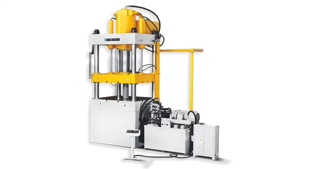
Start from the last step Geometry
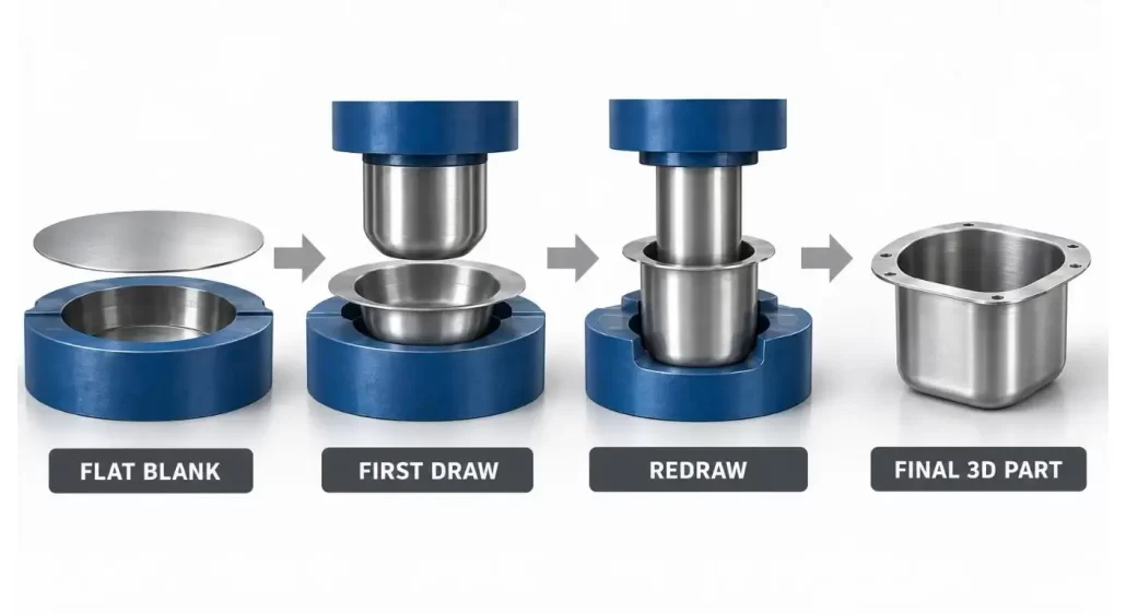
First, the forming problem areas need to be identified by looking at what geometric characteristics cause forming problems. A shallow tray can be made with one draw whereas a deep housing with a narrow radius and with different wall depths or multiple flanges may need several operations.
Check the drawing for draw depths, corner radius, undercuts, openings and surface quality required. Also ensure that trimming, piercing, restriking or calibration will be done in the same production line.
Equipment should allow for adequate stroke and daylight/work area for the entire tool. Even a machine that has sufficient tonnage may be wrong if the die will not fit or the part cannot be safely released from the die.
The selection of the tonnage is based on Study Material Flow.
How the blank moves through the die is affected by material grade, thickness and rolling direction. Each of the different materials (aluminum, stainless steel, high-strength steel and titanium) has varying forming limits and springback characteristics.
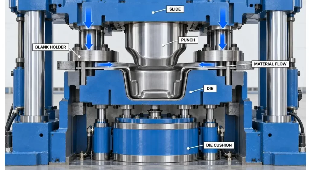
The forming resistance, blank-holder force, friction and contact area between the tool and material are all factors that should be considered in tonnage calculations. Peak force shouldn’t be considered as one number, but as a point on the stroke.
In deep three dimensional parts, if too much blank holder pressure is applied, it will hinder the flow of the material and tear it. Too low a pressure could lead to the formation of wrinkles. It is therefore important that the press should have the correct cushion capacity and pressure control rather than just high tonnage.
Select the Press in Accordance with the Motion Required
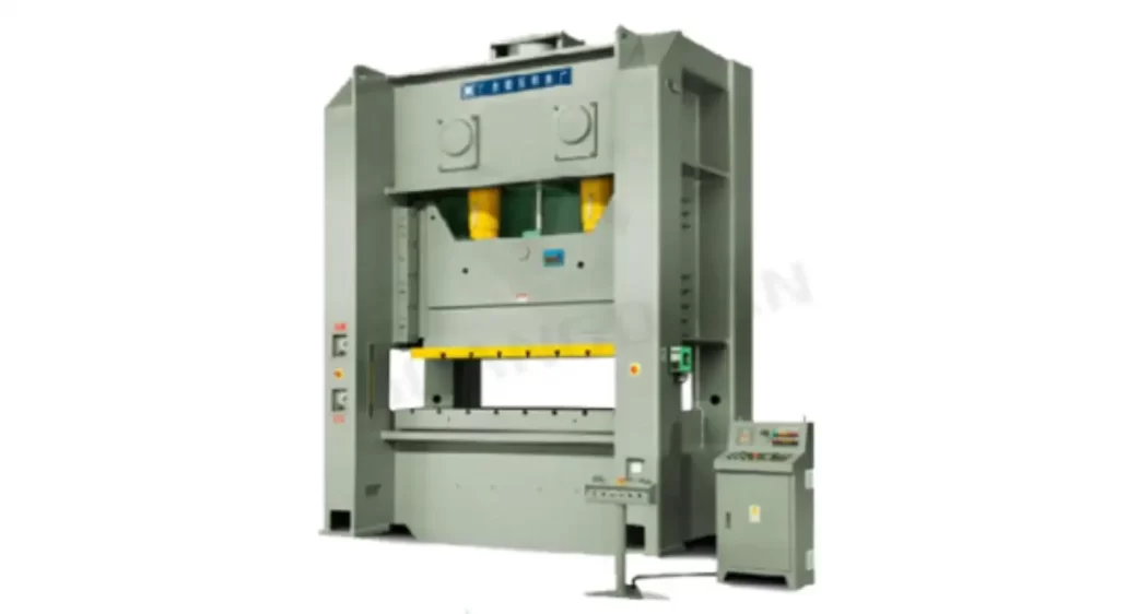
The mechanical press offers high production rate and repeatable slide motion. It is a consideration for stable volume, progressive or transfer stamping. The mechanical press types available from Guangduan are open-back, straight-side and multi-point.
Hydraulic Presses offer adjustable forming speed/dwell time, approach speed and force. These qualities allow for deep-drawing and large panel production and forming processes which involve controlled force over a long stroke. Purchasers of hydraulic presses are able to compare the available hydraulic press configurations.
Servo-controlled systems include programmable motion and process feedback. They are only useful if an optimized slide profile can be attained that will decrease cracking, improve material flow or boost production output.
| Forming Requirement | Suitable Equipment Feature | Parameter to Confirm |
| Deep, controlled draw | Hydraulic slide control | Forming speed and dwell |
| High-volume stamping | Mechanical drive | SPM and load curve |
| Large asymmetric part | Rigid straight-side frame | Off-center load |
| Controlled material flow | Programmable die cushion | Cushion force and stroke |
| Multiple operations | Transfer or multi-station line | Station pitch and timing |
| Sensitive surface | Controlled handling system | Gripper contact method |
Deconstruct and Form Stages of Difficult Geometry
Trying to make a complex shape in one operation can lead to excessive thinning/wrinkling or tool loads. Several stages of deformation occur in the drawing, redrawing, trimming and calibration stages.
The tooling engineer needs to specify the material flow in each step. Part geometry at the intermediate levels is important since it dictates how the part will be positioned, supported and moved to the next level.
Tooling or simulation can be used to determine if additional draw, restrike or annealing is necessary. An early controlled operation is generally less expensive than an out of control process after the production line is installed.
Co-ordinate the Press, Die and Cushion
The part geometry is determined by the die, while the speed and manner of die closing and material flow controlled by the press. These two systems need to be designed in conjunction with each other.
Check die weight, size of upper and lower tools, closing height and clamping and change over time. The slide and bolster assembly should be parallel, but not less than acceptable under the expected load.
Deep-draw tools might need a programmed force cushion, either hydraulic or pneumatic. Initial specification of ejectors and knockout devices and part-lifting systems should also be included. They need not be regarded as insignificant pieces of equipment which can be added on to the designed machine.
Apply simulation for decision-making
Even before the production tooling is finished forming simulation can provide estimates for thinning, strain, wrinkling, springback and required force. It will be most valuable if using realistic material data, friction and tool geometry.
Blank shape, draw beads, radii, forming stages and press capacity can be considered based on simulation results. They should be confirmed via testing as physical tests may show different behaviour of the lubrication and different material batches and tool surfaces.
It is NOT intended to create a pretty colour map. To minimize the uncertainty prior to committing to the press, die and automation layout.
Schedule Part Transfer in 3D
Feeding a flat blank is fairly simple. The first forming stage may result in a deep, unstable, hot or difficult-to-hold part. The geometry at each station changes and needs to be taken into consideration when transferring to a different one.
The component may need to be lifted, rotated and repositioned to this by the robot or three axis transfer system. The stiffness of parts, surface protection, part orientation and location of scrap or lubricant are all considerations for the design of a gripper.
Guangduan’s multi-station press line of 1250 ton, is a combination press with three-dimensional conveying, finished part discharging and sheet handling and servo feeding. This is a good example of the need for transfer equipment to be planned as part of the forming process.
Forming Process is monitored.
Having a press recipe stored isn’t enough for a stable process. Parameters that can be used for useful monitoring are the force, the slide position, the cushion pressure, the motor load, the die temperature and the transfer status.
Force-displacement monitoring will detect changes from improper blanks, double feeding, tool wear or lubrication change. The selection of sensors should be in line with the risk of defect and traceability needed.
Guangduan’s metal-forming application solutions illustrate how presses, sensors, transfer equipment and production monitoring can be combined to become part of a larger manufacturing system.
Verify Part AND Equipment Together
Machine functions and the entire sequence of forming should be tested at the factory. Use production tooling and material if possible to test the equipment.
Check part size, wall thinning, cracks and wrinkles, springback, surface marks. Simultaneously measure press force, cushion behavior, slide parallelism, cycle time and transfer repeatability.
Testing should be repeated cycles not one good sample. One successful trial is sufficient to determine that a part can be made; repeated trials will help determine that the process is stable.
| Inspection Area | Acceptance Focus | Verification Method |
| Final geometry | Dimensions within tolerance | CMM or inspection fixture |
| Wall condition | No excessive thinning | Thickness measurement |
| Surface | No cracks, folds or tool marks | Visual inspection |
| Press performance | Stable force and position | Cycle-data review |
| Transfer | Repeatable placement | Continuous production test |
| Output | Required cycle time achieved | Timed production run |
Conclusion
There are several elements that must be coordinated with each other when selecting 3D metal forming equipment, such as part geometry, material behavior, press motion, as well as tooling and automation. Tonnage is not the only factor that can be used to indicate whether the machine will form the component consistently.
Processes related specification, simulation assisted tooling plan and repeated production trial minimize project risk. These also give a better basis for future part families and expansion in production.
FAQs
Q1. What is the difference between 3D metal forming and 3D metal printing?
No – because they are reshaping an existing sheet, tube or billet of metal by plastic deforming. Metal printing is a method of creating a component layer by layer.
Q2. Which press should you use for more complicated 3D parts?
Hydraulic presses are suitable for a wide range of deep drawing and controlled force applications, and mechanical presses are capable of high-speed, repetitive stamping. It is a matter of geometry, material and production volume that determines which is the correct choice.
Q3. Is it possible to produce a complex part by a single process?
There are shallow areas that may be done in a single stroke. Multiple drawing, trimming and calibration steps are required for deep or irregular geometries.
Q4. Why is a die cushion important?
Cushion is used to regulate blank-holder force and the flow of material during drawing. The force may tear or wrinkle if it is not correct.
Q5. When the presses are tested should production tooling be used?
Yes, whenever practical. Testing with the die and material which it is intended to use in production gives more useful evidence than pressing without any production load.
CONTACT US


Guangdong Metal Forming Machine Works Co., Ltd.
We are always providing our customers with reliable products and considerate services.
If you would like to keep touch with us directly, please go to contact us
-

Home
-

Tel
-

Email
-

Contact